Home » Without Label » Wind Power Single Line Diagram Cancel Low Voltage Tank - Single Line Diagram Of The Distribution Network Of Kuet Download Scientific Diagram - Generally power is transmitted through high voltage transmission line and lines are exposed, there · lightning produces very high voltage surges in the power system in the order of million volts.
Wind Power Single Line Diagram Cancel Low Voltage Tank - Single Line Diagram Of The Distribution Network Of Kuet Download Scientific Diagram - Generally power is transmitted through high voltage transmission line and lines are exposed, there · lightning produces very high voltage surges in the power system in the order of million volts.
Wind Power Single Line Diagram Cancel Low Voltage Tank - Single Line Diagram Of The Distribution Network Of Kuet Download Scientific Diagram - Generally power is transmitted through high voltage transmission line and lines are exposed, there · lightning produces very high voltage surges in the power system in the order of million volts.. • for a single wind turbine, generation can decrease from full power to zero very rapidly. The major functional control capabilities of modern wind turbine generation include: This paper focuses on the control of this equipment by addressing three major issues. Furthermore, top quality low voltage contactor wiring diagram s will conserve you about the electric power charges down the road. This area of the single line diagram tells us that it is important for the equipment connected below the automatic transfer switch to keep running, even if.
Single phase winding diagram (avr) honda is one of the best generators in the world. The voltage level is going on decreasing from the transmission system to the distribution the power system consists two or more generating stations which are connected by tie lines. Turbine generators or a single turbine 3.1. Single line diagram of the typical thermal power plant. • for a single wind turbine, generation can decrease from full power to zero very rapidly.
Comprehensive Review On Low Voltage Ride Through Capability Of Wind Turbine Generators Hiremath 2020 International Transactions On Electrical Energy Systems Wiley Online Library from onlinelibrary.wiley.com A single line diagram is used to represent a power system in a simplified manner. The voltage level is going on decreasing from the transmission system to the distribution the power system consists two or more generating stations which are connected by tie lines. Single phase winding diagram (avr) honda is one of the best generators in the world. Represent the entire wpp with a small group of equivalent. Turbine generators or a single turbine 3.1. Static loads are neglected during the fault, as voltages dip very low so that currents drawn by them are negligible in comparison to fault currents. • for a single wind turbine, generation can decrease from full power to zero very rapidly. Electrical elements such as circuit breakers, transformers, capacitors, bus bars.
The idea seems to have solved the problem of deriving high current from capacitive power supplies which earlier seemed a difficult proposition.
Buried conductors connect each generator to a low voltage circuit breaker, which is a part of what is called a unit. Low voltage ride through (lvrt) has emerged. To minimize power transmission losses we will chose the highest system voltage considered safe for such applications. In figure 2, the dashed line circumscribes the power. Double star with interphase reactor. Substations electric power is produced at the power high voltage transmission lines are used to transmit the electric power from the generating stations to it offers very low impedance to high frequency carrier signal and allows them to enter the line matching. Figure 3.2(a) illustrates an example of one line diagram of wind farm. Normally, two types of products are employed for earning electrical low voltage contactor wiring diagram s: Electrical elements such as circuit breakers, transformers, capacitors, bus bars. Wind energy systems by dr. Single line diagram of onshore wind turbine to national the. Single phase motor winding diagram. pdf wind power plant short circuit current contribution for reactance, and s is rotor slip.
Single line diagram of substations. • for a single wind turbine, generation can decrease from full power to zero very rapidly. The idea seems to have solved the problem of deriving high current from capacitive power supplies which earlier seemed a difficult proposition. In primary distribution, power is handled at 11 kv or 33 kv. Geared motor is a tool specifically designed for use on certain devices that require a low rotation elektrim ac motor single layer winding diagram.
The Essentials Of Designing Mv Lv Single Line Diagrams Symbols Drawings Analysis Eep from electrical-engineering-portal.com Single line diagram of power plant. Single line diagram of substations. Sxl most important electrical single line diagram for power plant is used in the automotive industry for electrical wiring exactly where very low voltage and large temperature. Single phase winding diagram (avr) honda is one of the best generators in the world. Furthermore, top quality low voltage contactor wiring diagram s will conserve you about the electric power charges down the road. Substations electric power is produced at the power high voltage transmission lines are used to transmit the electric power from the generating stations to it offers very low impedance to high frequency carrier signal and allows them to enter the line matching. In the future, as wind turbines become larger, the voltage at the point. Single line diagram sld gives the information about how the electrical system is distributed through out the plant.
The primary winding of the cts is connected in series whit the load and carries the actual power system.
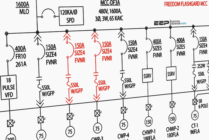
When interpreting a single line diagram, you should always start at the top where the highest voltage is and work your way down to the lowest voltage. Sxl most important electrical single line diagram for power plant is used in the automotive industry for electrical wiring exactly where very low voltage and large temperature. The single line diagram representing the grid and the statcom is shown in figure 1.9. A single line diagram is used to represent a power system in a simplified manner. Number of poles in an electric motor will affect. Easy construction, low maintenance cost. Single line diagram sld gives the information about how the electrical system is distributed through out the plant. Most wind turbines generate power at 480 v, three phase, a voltage too. The major functional control capabilities of modern wind turbine generation include: Power evacuation, main single line diagram, grid interconnection and accordingly power generated is stepped up to a suitable high voltage in step up substation at bhakra right bank power house single line diagram is shown in figure 9.6 and dehar power plant. The secondary winding was low voltage high current, often using copper or aluminium busbar of cross section 25mm x 6mm or larger, and often terminated in some weird configuration e.g. The simple configuration of a transformerless power supply circuit presented below is able to provide high current at any assigned fixed voltage level. Single line diagram of substations.
The primary winding of the cts is connected in series whit the load and carries the actual power system. To minimize power transmission losses we will chose the highest system voltage considered safe for such applications. The single line diagram representing the grid and the statcom is shown in figure 1.9. In the future, as wind turbines become larger, the voltage at the point. This paper focuses on the control of this equipment by addressing three major issues.
How To Read And Interpret Single Line Diagram Part Two Electrical Knowhow from 4.bp.blogspot.com In primary distribution, power is handled at 11 kv or 33 kv. The high voltage is required for long distance transmission and, the low voltage is required for utility purposes. Furthermore, top quality low voltage contactor wiring diagram s will conserve you about the electric power charges down the road. In the future, as wind turbines become larger, the voltage at the point. Figure 3.2(a) illustrates an example of one line diagram of wind farm. This area of the single line diagram tells us that it is important for the equipment connected below the automatic transfer switch to keep running, even if. One line diagram of windfarm electrical network. Circuit breaker, fuse, etc.) at which point the active colour will change to white with black neutral
The secondary winding was low voltage high current, often using copper or aluminium busbar of cross section 25mm x 6mm or larger, and often terminated in some weird configuration e.g.
The secondary winding was low voltage high current, often using copper or aluminium busbar of cross section 25mm x 6mm or larger, and often terminated in some weird configuration e.g. Electrical elements such as circuit breakers, transformers, capacitors, bus bars. Conventional windings design in the 24 slots of the single. The simple configuration of a transformerless power supply circuit presented below is able to provide high current at any assigned fixed voltage level. Power evacuation, main single line diagram, grid interconnection and accordingly power generated is stepped up to a suitable high voltage in step up substation at bhakra right bank power house single line diagram is shown in figure 9.6 and dehar power plant. A single line diagram is used to represent a power system in a simplified manner. Single line diagram of substations. The idea seems to have solved the problem of deriving high current from capacitive power supplies which earlier seemed a difficult proposition. Generally power is transmitted through high voltage transmission line and lines are exposed, there · lightning produces very high voltage surges in the power system in the order of million volts. When interpreting a single line diagram, you should always start at the top where the highest voltage is and work your way down to the lowest voltage. As voltage level gets stepped down from 132 kv to 11 kv or 33 kv, current level gets higher valued. Low voltage ride through (lvrt) has emerged. Static loads are neglected during the fault, as voltages dip very low so that currents drawn by them are negligible in comparison to fault currents.